Load balancing
Network Address Translation (NAT)
This page applies to:
- HAProxy ALOHA - all versions
With Network Address Translation (NAT) enabled, the HAProxy ALOHA appliance can replace the following properties of incoming TCP, UDP, and ICMP packets:
- the source IP address
- the source port
- the destination IP address
- the destination port
Why use Network Address Translation? NAT makes it possible to change the routing information inside packets, which lets you route traffic to a different IP address or port than it was originally destined for. For example, you could receive TCP or UDP traffic at the HAProxy ALOHA’s IP address; then, based on your NAT rules, change the destination address to be a backend server’s IP address and forward the packets to that server. It’s the same as how a router works. But defining a static routing rule like that isn’t the most powerful aspect. More often, you won’t route traffic to a single backend server, but instead load balance traffic across multiple servers. That’s why you’ll typically combine using NAT rules with using LVS, which is a Layer 4 load balancer built into HAProxy ALOHA.
LVS has partial NAT functionality already built in. It can change the destination IP address of incoming packets, and it can do so on the fly to load balance across backend servers. But LVS doesn’t have the ability to change the source IP address of packets, and we need a way to do that to ensure that traffic returning from servers is routed back through HAProxy ALOHA, rather than directly back to the client’s source IP address. Without a way to change the source IP address when using LVS, you’d need to configure backend servers to use the HAProxy ALOHA VIP address as their default gateway, which is more complex.
By using the NAT tab in combination with LVS on the LB Layer4 tab, you can load balance traffic, ensure it returns to the load balancer, and avoid changing the default gateway on the backend servers. You’ll most often use the NAT tab to modify the source IP address on incoming packets to be the HAProxy ALOHA’s VIP. You won’t typically use it to change the destination IP address, since that’s already handled by LVS on the LB Layer4 tab.
On this page, we’ll cover how the NAT tab works generally. Once you’ve grasped how the NAT tab works, you may find these tutorials helpful:
Multiple ways to support TCP and UDP
HAProxy ALOHA also supports TCP and UDP load balancing on its LB Layer7 tab, which uses HAProxy instead of LVS. You might prefer that for better session tracking, logging, and statistics. You might prefer LVS if you require the utmost speed, since it routes TCP and UDP packets without any overhead.
NAT tab layout Jump to heading
NAT rules convert into iptables rules, but using the NAT tab is much simpler than writing iptables rules yourself. At first, the NAT rules table is empty. Click the + icon (Insert new rule) to begin to define a rule.

For each rule, you can set the following fields.
| Field | Description |
|---|---|
| IN | The network interface on which to receive incoming packets. |
| OUT | The network interface on which to send outgoing packets. |
| Protocol | The protocol to match (TCP, UDP, or ICMP). This is required if you set Before - Port to match a source or destination port. |
| Related Only | Enable to apply the rule to packets with related connections only, meaning new packets triggered by an active connection. |
| Before - Source | Which packets to match depending on their source IP address. Set this to any or leave blank to match any source IP address. |
| Before - Port | Which packets to match depending on their source port. Set this to any or leave blank to match any source port. You can set a single port like 8000, or a port range like 50000-51000. If you set this, also set Protocol to TCP, UDP, or ICMP. |
| Before - Destination | Which packets to match depending on their destination IP address. Set this to any or leave blank to match any destination IP address. |
| Before - Port | Which packets to match depending on their destination port. Set this to any or leave blank to match any destination port. You can set a single port like 8000, or a port range like 50000-51000. If you set this, also set Protocol to TCP, UDP, or ICMP. |
| After - Source | A new source IP address to set on matched packets. To make no change, you can set this to same or leave it blank. |
| After - Port | A new source port to set on matched packets. To make no change, you can set this to same or leave it blank. |
| After - Destination | A new destination IP address to set on matched packets. To make no change, you can set this to same or leave it blank. |
| After - Port | A new destination port to set on matched packets. To make no change, you can set this to same or leave it blank. |
NAT traffic flow Jump to heading
After your NAT rules modify a packet’s addresses — typically, just changing the packet’s source address to be the HAProxy ALOHA’s VIP — the changed packet is then processed by LVS, which sends it to a backend server. When the server prepares its response, it reverses the source address and the destination address, which results in sending the response back to HAProxy ALOHA. When the HAProxy ALOHA appliance receives the server’s response, it replaces the destination address with the original client IP address and sends the packet back to the client.
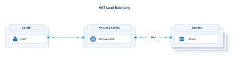
By using NAT to change the source address in packets, you ensure that server responses flow back to HAProxy ALOHA. Because NAT operates at the packet level, you can use it for Linux and Windows backend servers. Backend servers can keep the network’s external gateway as their default gateway. Disadvantages include that it reduces the number of connections that HAProxy ALOHA can support, due to needing to use more ports.
Optionally, instead of configuring source NAT (HAProxy ALOHA NAT tab), you can set HAProxy ALOHA to be the default gateway on the backend server. That accomplishes the same thing and would use fewer ports on HAProxy ALOHA, at the cost of a slightly more complex setup on the backend server (i.e. needing to change the default gateway).
Here’s a recap of how traffic flows when you use NAT to change the source IP address of incoming packets:
-
The client connects to your application at the configured virtual IP address (VIP). HAProxy ALOHA listens at that address and receives the packets.
-
Through NAT rules, the packet’s source IP address is translated from the client’s IP to the HAProxy ALOHA IP address.
-
Through LVS, the packet’s destination IP address is translated from the HAProxy ALOHA VIP to the real IP of one of the backend servers. The packets are sent on the outgoing network interface.
-
The backend server accepts the request to its IP.
-
The backend server sends its response to HAProxy ALOHA because its address is set as the source IP in the packet.
-
HAProxy ALOHA performs the reverse NAT before relaying the response to the client.
Display NAT rules results Jump to heading
NAT rules are stored in the /etc/natrules/natrules.cfg file.
In the natrules.cfg entry below, TCP packets targeted for 172.30.100.0:3389 have their source IP address changed to 10.11.100.20 and are sent to device eth1.
natrules.cfgtext
natrules.cfgtext
To display the results of NAT rules, use this command:
nix
nix
Example output from preceding example natrules.cfg entry:
outputtext
outputtext