High availability
Active/Active clustering
In an active-active cluster, two or more HAProxy Enterprise nodes receive traffic in a load-balanced rotation. This allows you to scale out your load-balancing capacity. There are several ways to achieve this setup, including:
- Using DNS round-robin
- Deploy two tiers of load balancers
- Using Anycast with the HAProxy Enterprise Route Health Injection module (see Route Health Injection)
Option 1: DNS round-robin Jump to heading
GSLB for DNS round-robin
You can use an HAProxy Enterprise server for DNS round-robin. See GSLB.
To create an active-active cluster of load balancers, you can use DNS round-robin to send traffic to each load balancer in a rotation.
To remove unhealthy HAProxy Enterprise nodes from round-robin load-balancing rotation, you need a way to detect failure. If your DNS server supports health checking upstream servers, you can use that feature to remove unhealthy nodes. However, in this section, we assume that your DNS server does not support health checking. Instead, you need to configure the HAProxy Enterprise VRRP module to assign a virtual IP address to each load balancer. In the event that one of your load balancers fails, its virtual IP address will transfer to a healthy load balancer node.
A side effect of this failover is that your healthy node, which had been receiving its own share of traffic already, will temporarily take on more traffic until the other node recovers.
In this guide, we set up two load balancers: both actively receiving traffic.
Configure VRRP Jump to heading
-
Install the VRRP module using your system’s package manager on both HAProxy Enterprise nodes that will participate in your load balancer cluster:
nixsudo apt-get install hapee-extras-vrrpnixsudo apt-get install hapee-extras-vrrpnixsudo yum install hapee-extras-vrrpnixsudo yum install hapee-extras-vrrpnixsudo zypper install hapee-extras-vrrpnixsudo zypper install hapee-extras-vrrpnixsudo pkg install hapee-extras-vrrpnixsudo pkg install hapee-extras-vrrp -
On the first load balancer, edit the file
/etc/hapee-extras/hapee-vrrp.cfg. By default, this file is configured for an active-standby cluster. Replace thevrrp_instanceblock with the following contents.- Replace the
interfacelines with the name of the network interface on which this server receives traffic. - Replace the IP addresses listed in the
virtual_ipaddress_excludedblocks with addresses you’d like to use to receive traffic. These new addresses should fall within the interface’s IP subnet, but should not be assigned to any server already.
hapee-vrrp.cfgtextvrrp_instance vrrp_1 {interface enp0s8 # Change network interface namestate MASTERvirtual_router_id 51priority 101virtual_ipaddress_excluded {192.168.50.10 # NEW IP address}track_interface {enp0s8 weight -2 # Change network interface name}track_script {chk_sshdchk_lb}}vrrp_instance vrrp_2 {interface enp0s8 # Change network interface namestate BACKUPvirtual_router_id 52priority 100virtual_ipaddress_excluded {192.168.50.11 # NEW IP address}track_interface {enp0s8 weight -2 # Change network interface name}track_script {chk_sshdchk_lb}}hapee-vrrp.cfgtextvrrp_instance vrrp_1 {interface enp0s8 # Change network interface namestate MASTERvirtual_router_id 51priority 101virtual_ipaddress_excluded {192.168.50.10 # NEW IP address}track_interface {enp0s8 weight -2 # Change network interface name}track_script {chk_sshdchk_lb}}vrrp_instance vrrp_2 {interface enp0s8 # Change network interface namestate BACKUPvirtual_router_id 52priority 100virtual_ipaddress_excluded {192.168.50.11 # NEW IP address}track_interface {enp0s8 weight -2 # Change network interface name}track_script {chk_sshdchk_lb}}This creates two virtual IP addresses:
192.168.50.10and192.168.50.11. The first has itsstateset toMASTER, while the second is set toBACKUP. This means that this load balancer owns the first IP address but will only bind to the second IP address as a backup, meaning when its primary owner fails. - Replace the
-
On the other load balancer, configure the VRRP module in a similar way, but swap the
statevalues so that the firstvrrp_instanceblock is set toBACKUP, while the second is set toMASTER. Also, swap thepriorityvalues. In this way, each load balancer is a backup for the other. If one fails, its virtual IP will transfer to the other node, which will at that point answer requests from both addresses until the failed node recovers.hapee-vrrp.cfgtextvrrp_instance vrrp_1 {interface enp0s8 # Change network interface namestate BACKUPvirtual_router_id 51priority 100virtual_ipaddress_excluded {192.168.50.10 # NEW IP address}track_interface {enp0s8 weight -2 # Change network interface name}track_script {chk_sshdchk_lb}}vrrp_instance vrrp_2 {interface enp0s8 # Change network interface namestate MASTERvirtual_router_id 52priority 101virtual_ipaddress_excluded {192.168.50.11 # NEW IP address}track_interface {enp0s8 weight -2 # Change network interface name}track_script {chk_sshdchk_lb}}hapee-vrrp.cfgtextvrrp_instance vrrp_1 {interface enp0s8 # Change network interface namestate BACKUPvirtual_router_id 51priority 100virtual_ipaddress_excluded {192.168.50.10 # NEW IP address}track_interface {enp0s8 weight -2 # Change network interface name}track_script {chk_sshdchk_lb}}vrrp_instance vrrp_2 {interface enp0s8 # Change network interface namestate MASTERvirtual_router_id 52priority 101virtual_ipaddress_excluded {192.168.50.11 # NEW IP address}track_interface {enp0s8 weight -2 # Change network interface name}track_script {chk_sshdchk_lb}} -
Start the
hapee-extras-vrrpservice on both servers:nixsudo systemctl start hapee-extras-vrrpsudo systemctl enable hapee-extras-vrrpnixsudo systemctl start hapee-extras-vrrpsudo systemctl enable hapee-extras-vrrp -
Edit your HAProxy Enterprise configurations to listen on the virtual IP addresses. Note that you must append the field
transparent, indicating that the address will be bound even if it does not belong to the local machine, which is necessary since the virtual IP will float to the active load balancer.haproxyfrontend myfrontendmode httpbind 192.168.50.10:80 transparentbind 192.168.50.11:80 transparentdefault_backend web_serversbackend web_serversserver s1 192.168.50.20:80haproxyfrontend myfrontendmode httpbind 192.168.50.10:80 transparentbind 192.168.50.11:80 transparentdefault_backend web_serversbackend web_serversserver s1 192.168.50.20:80Alternatively, if you prefer to not add
transparentto everybindline, you can set the kernel parameterip_nonlocal_bind. Edit the file/etc/sysctl.confand add the linenet.ipv4.ip_nonlocal_bind=1:sysctl.confininet.ipv4.ip_nonlocal_bind=1sysctl.confininet.ipv4.ip_nonlocal_bind=1Then run
sudo sysctl -pto reload the configuration.As a third option, you can listen on all IP addresses assigned to the server by omitting the IP address:
haproxyfrontend myfrontendmode httpbind :80default_backend web_servershaproxyfrontend myfrontendmode httpbind :80default_backend web_servers
In essence, we have created an active-active cluster by creating two active-standby clusters, one in each direction. Each load balancer has an active IP address, but also serves as a standby server for the other IP address.
Configure DNS round-robin Jump to heading
DNS allows you to rotate which IP address is returned in response to a DNS query. When clients request your service by its domain name, they will receive the IP address of the next load balancer in the list. Clients tend to cache DNS results, so once a client receives a DNS answer, it will likely continue making requests to the same load balancer until the DNS answer expires.
Create an A record for each load balancer IP address. For example, consider the following DNS zone file:
text
text
Depending on your DNS server, you may need to enable load-balancing of the A records. It is also a good idea to set a shorter TTL for these records to avoid staying cached in intermediate nameservers for long.
Option 2: Two tiers of load balancers Jump to heading
To create an active-active cluster of load balancers, you can place another tier of HAProxy Enterprise load balancers in front. These load balancers operate at Layer 4, the Network layer, and load balance the load balancers. Because HAProxy Enterprise has the ability to check the health of the lower tier of load balancers, it can remove unhealthy nodes as needed.

Deploy Layer 7 load balancers Jump to heading
Create a tier of load balancers that will, themselves, be load-balanced:
-
Deploy at least two servers to host HAProxy Enterprise. Add one or more static IP addresses to each server.
-
Install HAProxy Enterprise on each server.
-
Configure them to receive traffic on the assigned IP addresses and relay it to backend application servers. Other than the addresses, their configurations should match.
Deploy Layer 4 load balancers Jump to heading
Create a tier of load balancers that will load balance the layer 7 HAProxy Enterprise servers:
-
Deploy one or more servers to host HAProxy Enterprise. These will load balance the other load balancers.
-
If you deploy multiple load balancers in this tier, configure them in active-standby mode.
-
Configure them to relay traffic to the layer 7 load balancers. In the following example, a
listensection defines the pool of upstream load balancers:haproxylisten load_balancer_clustermode tcpbind :80option tcplogbalance roundrobinserver lb1 192.168.1.25:80 checkserver lb2 192.168.1.26:80 checkhaproxylisten load_balancer_clustermode tcpbind :80option tcplogbalance roundrobinserver lb1 192.168.1.25:80 checkserver lb2 192.168.1.26:80 check
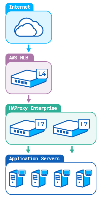
Active/active setup on AWS Jump to heading
To create an active-active cluster of HAProxy Enterprise load balancers in AWS, you can place a Network Load Balancer in front. This load balancer operates at Layer 4, the Network layer, and load balances the HAProxy Enterprise load balancers. Because AWS Network Load Balancer can check the health of the lower-tier of load balancers, it can remove unhealthy load balancers as needed.
We will:
- Create a virtual network dedicated to your AWS account (VPC).
- Deploy several HAProxy Enterprise AMIs.
- Create an AWS target group.
- Create an AWS Network Load Balancer in a single Availability Zone.
- Test the setup.
Create a VPC Jump to heading
You can launch HAProxy Enterprise nodes in a Virtual Private Cloud (VPC), which is a virtual network similar to a traditional network.
-
Open the Amazon VPC console, then click Launch VPC Wizard.
-
Create a VPC with a Single Public Subnet with Public subnet’s Availability Zone set to the availability zone of your choice, for example,
eu-west-3a. In other fields, keep the default values or select other values that better suit your needs. -
In the Virtual Private Cloud section on the left, select Your VPCs, then write down the ID of the new VPC. For example,
vpc-0deecc96935b9ef73.
Deploy HAProxy Enterprise AMIs Jump to heading
You can launch HAProxy Enterprise nodes directly from the AWS Marketplace. Create two or more HAProxy Enterprise nodes on AWS, with the following characteristics:
| Field | Value |
|---|---|
| Software version | The version of HAProxy Enterprise. |
| Region | Region to which your Availability Zone belongs. |
| VPC Settings | ID of the VPC you previously created. For example, vpc-0deecc96935b9ef73. |
| Subnet Settings | Public subnet that belongs to the VPC. |
| Security Group Settings | Create a new security group based on seller settings for the first HAProxy Enterprise node. Then select the same security group for other nodes. |
| Key Pair Settings | Create a new EC2 key pair, or select an existing one. Select the same key pair for all HAProxy Enterprise nodes. |
In other fields, keep the default values or select other values that better suit your needs.
Create an AWS target group Jump to heading
A target group routes requests to one or more registered targets, such as HAProxy Enterprise nodes, using the TCP protocol and the port number that you specify.
-
Open the Amazon EC2 console.
-
In the Load Balancing section on the left, select Target Groups.
-
Create a target group with the following characteristics, then click Next.
Field Value Target type Instances Protocol TCP VPC The virtual private cloud (VPC) you created previously. For example, vpc-0deecc96935b9ef73.In the other fields, keep the default values or select other values that better suit your needs.
-
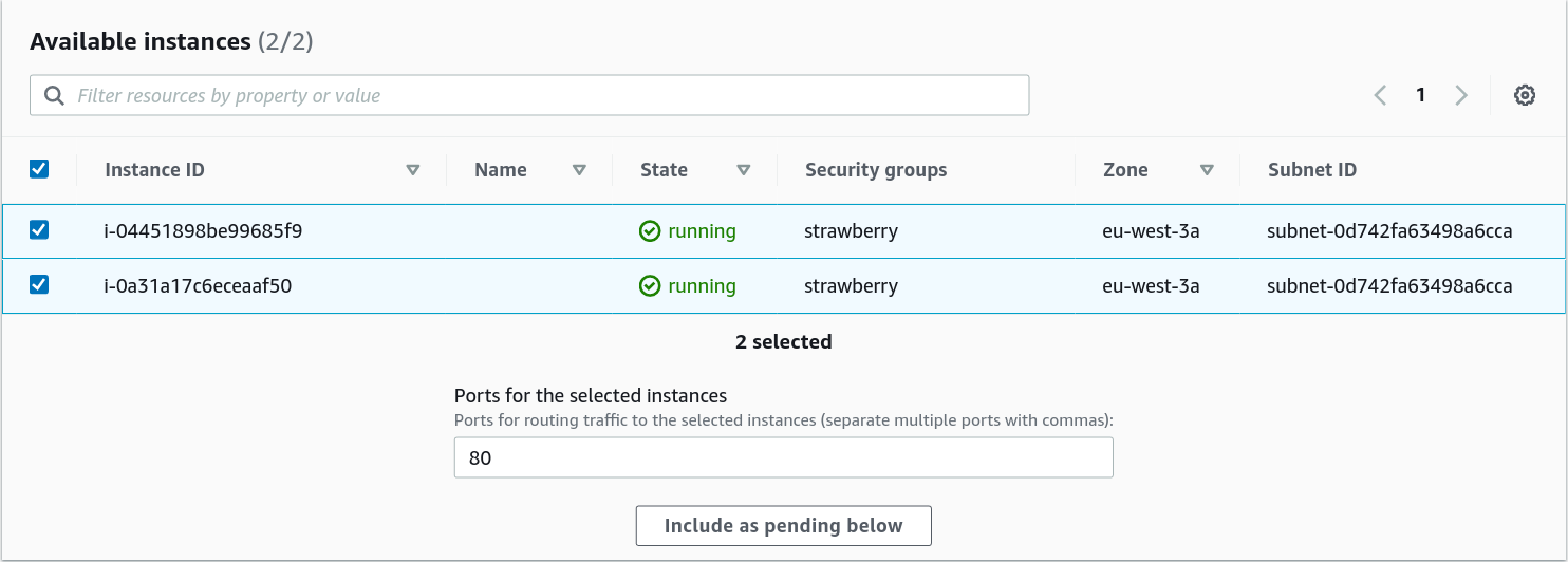
On the Register targets page, select the HAProxy Enterprise nodes you created previously. Then click Include as pending below.
-
Click Create target group.
Create an AWS Network Load Balancer Jump to heading
The AWS Network Load Balancer selects a target HAProxy Enterprise node using a flow hash algorithm based on the source and destination IP addresses and ports, the protocol, and the TCP sequence number.
-
In the Load Balancing section on the left, select Load Balancers.
-
Create a Network Load Balancer with the following characteristics:
Field Value Scheme Internet-facing. VPC The virtual private cloud (VPC) you created previously. For example, vpc-0deecc96935b9ef73.Mappings Select your Availability Zone and the corresponding subnet. Listeners Default (a listener that accepts TCP traffic on port 80). Default action Select the target group you created previously. In the other fields, keep the default values or select other values that better suit your needs.
-
Click Create load balancer.
Test your setup Jump to heading
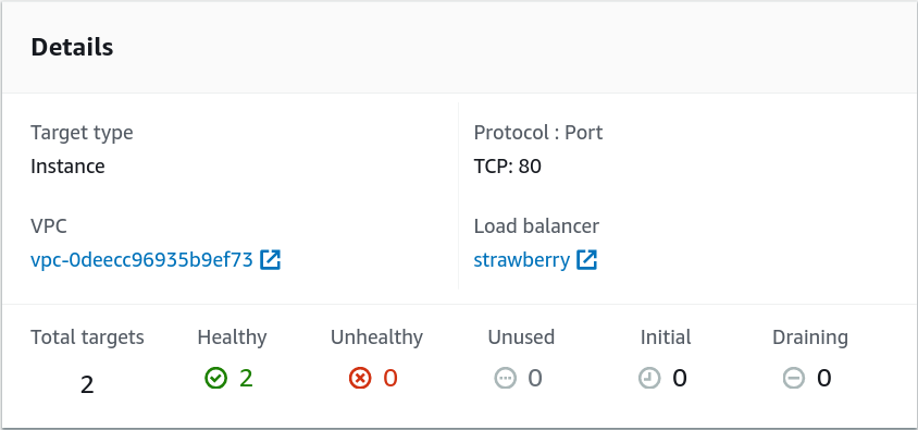
Once you have created a Network Load Balancer, wait a few minutes and check that the HAProxy Enterprise nodes in your target group have passed the initial health check. You can then test that the layer 4 AWS Network Load Balancer sends traffic to your layer 7 HAProxy Enterprise load balancers.
-
In the Load Balancing section on the left, select Target Groups.
-
Select the newly created target group, and check that your HAProxy Enterprise nodes are ready.
-
In the Load Balancing section on the left, select Load Balancers.
-
Select the newly created load balancer.
-
Copy the DNS name of the load balancer and paste it into the address field of a web browser.
For example,
strawberry-f9f565c7eb5b3cd3.elb.eu-west-3.amazonaws.com.The browser displays the statistics page of your HAProxy Enterprise node.
If you launched nodes with different versions of HAProxy Enterprise, paste the DNS name of the Network Load Balancer into the address field of another web browser or in a private browser window. The browser should display the statistics page of one of your other HAProxy Enterprise nodes, which runs another version of HAProxy Enterprise. Since each TCP connection is routed to a single target as long as the connection is active, you may have to try connecting several times.
You can now:
- configure your backend server pool.
- edit the
frontendsection of your HAProxy configuration file (each AWS Network Load Balancer in the Availability Zone has a static IP). - edit the
backendsection of your HAProxy configuration file. - copy the configuration file to all HAProxy Enterprise nodes in the AWS target group.
See also Jump to heading
Do you have any suggestions on how we can improve the content of this page?